The future of Vertex graphics
We have always offered Master´s Thesis opportunities to university students to support their academic and professional qualifications. There are more than 40 Master´s Theses completed for Vertex during the years. The research results are implemented in our product development to provide cutting-edge software solutions for our customers. In the “My Master´s Thesis Journey” blog series, our young professionals tell about their Master´s theses and what they have learned and accomplished during the journey.

Backgrounds
My journey with Vertex Systems started with a summer job in 2017. After many summers and part-time work while studying, the time was drawing near to begin work on my Master’s thesis. I had previously worked exclusively on the online model sharing service, Vertex Showroom. My major was mathematics, so finding a suitable topic was the first challenge. I had grown interested in computer graphics while working on Showroom, which lead me from web development to the world of Vertex CAD software.
Since I had no previous experience with graphics, I started with implementing a physically-based rendering (PBR) material shader into the recently revamped Vertex graphics engine. For those interested in the topic, this post by Jeff Russell explains the basics of physically-based rendering well, without delving too deep into the technical details. In short, the new materials are more physically accurate in various lighting conditions than the previously used materials. After the PBR material implementation, I worked on proof-of-concept versions of screen space ambient occlusion and reflections to explore the quality that would be possible with current, battle-tested methods.
After these forays into computer graphics, I was excited and confident that this was the subject I wanted to dive into in my thesis. The goal was to improve the graphical quality of Vertex CAD products with a new lighting system. It was also deemed important that the new lighting system would run on older hardware too, since not everyone has the latest and greatest hardware. This is especially true today with the component shortages and ever-increasing prices of graphics cards. Additionally, if the work done for my thesis could be used to improve the graphics of Showroom in the future, that would be a nice bonus.
After some back-and-forth with the people at the Virtual reality and Graphics Architectures (VGA) group at Tampere University, I had a great supervisor and a topic. Keeping the specifications in mind, using signed distance fields seemed to be the most promising approach. A signed distance field (SDF) outputs the distance to the surface it represents, with the sign being positive outside and negative inside.
Interactive global illumination for static computer-aided design models using signed distance fields
That is the final title of my thesis. Quite a mouthful, isn’t it? Let’s break it down a bit. In the strictest sense of the term, global illumination means all effects arising from different objects in the scene affecting the rendering of the others, but usually only indirect lighting is called global illumination. Indirect lighting, also called bounce lighting, is light that is reflected onto a surface from other surfaces. This is in contrast to direct lighting, which is the light that hits a surface directly from a light source.
Since computing global illumination is a complex problem, some restrictions were put in place to make the scope of the thesis more feasible. The term interactive means that not all lighting has to be computed in real-time, allowing for precomputation. A rough preview should be available as fast as possible, though. The models are also assumed to be static, i.e. the geometry of the model doesn’t change or move. These restrictions allow us to generate a single discrete signed distance field (SDF) into a 3D texture to represent the model. The accuracy decreases the larger the model is physically, though, since the texture size is limited.
We can use this SDF representation of the model to compute various lighting effects. It makes sense to categorize reflections into two different categories, diffuse and specular reflections. Diffuse reflections happen when light enters a surface, reflecting from microscopic structures inside the material randomly before exiting. Diffuse reflections can reasonably be assumed to not depend on the viewing direction because of the randomness. An important concept in physically-based rendering is material roughness, which greatly affects specular reflections. Specular reflections depend heavily on the viewing direction. Perfectly smooth surfaces reflect light in a mirror-like fashion. Rougher surfaces spread the reflected light, making the reflection appear blurry.

Figure 1 From left to right: Diffuse reflections, then smooth and rough specular reflections
Photorealistic images with global illumination are usually generated by using ray tracing to follow the paths of light rays as they bounce from surfaces made of different materials. SDFs help with ray tracing. It is possible to safely move in the direction of the ray by the distance sampled from the SDF without hitting a surface, since we know that the nearest surface is exactly that far. The algorithm is called sphere tracing, and it allows for larger steps at empty spaces and smaller steps when closer to surfaces. The end result is reasonably performant ray tracing for the shape of the SDF, even using graphics cards that are over a half-decade old.

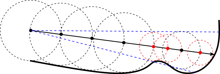
Figure 2. Sphere tracing. The circles represent the distances sampled from the SDF.
Sphere tracing can be used on the SDF of the model to precompute indirect diffuse lighting into a light map texture. This works because we assumed the model to be static and diffuse lighting to be viewpoint independent. The previously computed light map can be used as a lighting cache, so that we don’t have to explicitly compute multiple bounces of lighting. We get a noisy result instantly, which gets more accurate over time.
The sphere tracing algorithm is easy to expand to approximate cone tracing. Since the distance to the nearest surface is known, it is possible to include a cone angle and just check if the closest surface is nearer than the cone size at that point.

Figure 3 Cone tracing. The blue line is the cone, while the red points and circles represent a detected cone hit.
With approximate SDF cone tracing, we can compute soft shadows in real-time using a method presented by Sebastian Aaltonen at the Game Developers Conference (GDC) in 2018. I also developed a novel method for cone tracing specular reflections of varying roughness for the thesis. The cone size is determined by the roughness of the surface. The SDF is also sampled at multiple points inside the cone, with weighting derived again from the surface roughness. The color is sampled from a 3D light map texture containing diffuse reflections premultiplied with material properties.
Results and future possibilities
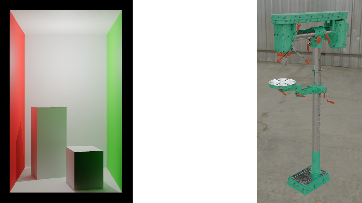
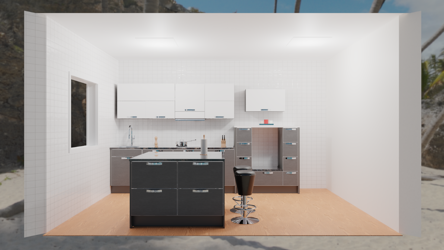
Now that we have covered the basics of the lighting system, it’s time to see it in action. The following images are rendered in real-time with Vertex CAD products after the indirect diffuse light precomputation. The precomputation takes under a minute using the latest hardware and several minutes with older hardware.


Figure 4 Result images rendered with Vertex CAD products
The results look pretty good, right? It bears remembering, though, that the precomputed lighting and the signed distance field are only correct if nothing moves or changes in the model. The accuracy is also better the smaller the model is.
Fortunately, there are multiple potential improvements to the system, which are detailed in my thesis. These include improving the performance, interactivity, scalability and quality. Signed distance fields also make implementing new physically-based rendering material types possible, like rough, transparent materials. It is also possible to add functionality to export the precomputed light maps to Showroom, which would increase the graphical quality there, too.
In short, the lighting system still needs polishing, but it shows real promise and offers plentiful possibilities for future development. And, since all the limitations have potential to be alleviated by some improvement or another, the future of next-generation Vertex graphics looks bright.
Read also other “My Master´s Thesis Journey” blog posts:
AI assisted document archiving
Intelligent assembly constrains
